Basic
Concepts: Components of data communication:
Communication:
To convey any message, data or thoughts from one place to another place using some medium is termed as a communication.
Components
of data communication:
1.
Sender
2.
Message
3.
Medium
4.
Receiver
5.
Protocols
6. Feedback
Sender:
Sender is the person who sends message.
Message:
Message is the information that is exchanged between sender and receiver
Medium:
Medium is the channel through which sender will communicate his message.
Receiver:
The person to whom the message is being sent is called ‘receiver’. Receiver is
the
person
who interprets the message.
Protocols: Protocols are some set of
rules followed by the sender and receiver for
communication.
Feedback: Response or reaction of the
receiver, to a message, is called ‘feedback’. Feedback
may be written or oral message, an action or simply,
silence may also be a feedback to a
message. Communication is said to be effective only when it
receives some feedback. Feedback,
actually,
completes the loop of communication.
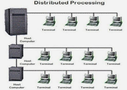
Distributed
processing: Distributed processing
accelerates processing by distributing the work
to
multiple computers that have been chosen to provide more processing power.
Distributed
processing
is a phrase used to refer to a variety of computer systems that use more than
one computer (or processor) to run an application.
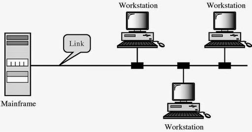
Line
configuration:
Line
configuration refers to the way two or more communication devices attached to a
link. Line
configuration
is also referred to as connection. A Link is the physical communication pathway
that
transfers data from one device to another. For communication to occur, two
devices must be
connected
in same way to the same link at the same time.
Types
of line configuration
1.
Point-to-Point.
2.
Multipoint.
Point-to-Point:
A
Point to Point Line Configuration Provide dedicated link between two devices
use actual
length
of wire or cable to connect the two end including microwave & satellite
link. Infrared remote control.

Multipoint
Configuration:
Multipoint
Configuration also known as Multidrop line configuration one or more than
two specific
devices share a single link capacity of the channel is shared. With shared
capacity, there can
be two possibilities in a Multipoint Line Configuration:·
1)Spatial Sharing:
If several devices can share the link simultaneously, it’s called Spatially shared line configuration
2)Temporal (Time) Sharing:
If users must take turns using the link , then it’s called Temporally shared or Time Shared Line Configuration
Topology:
The
term “Topology” refers to the way in which the end points or stations/computer
systems,
attached
to the networks, are interconnected. We have seen that a topology is
essentially a stable
geometric
arrangement of computers in a network.
Types
of topology:
(1)
Mesh topology.
(2)
Star topology.
(3)
Tree (Hierarchical) topology.
(4)
Bus topology.
(5)
Ring topology.
1.
Mesh Topology: In mesh topology each node is connected to all
other nodes. It is also called as fully connected mesh topology. The number of
connections in a full mesh = n(n - 1) / 2

2.
Star Topology:
In
a star topology, cables run from every computer to a centrally located device
called a HUB.
Star
topology networks require a central point of connection between media segment.
These central
points are referred to as Hubs. Hubs are special repeaters that overcome the electromechanical
limitations of a media. Each computer on a star network communicates with a central hub that resends the message either to
all the computers.

3.
Tree (Hierarchical) topology:
It
is similar to the star network, but the nodes are connected to the secondary
hub that in turn is connected to the central hub. The central hub is
the active hub. The active hub contains the repeater,
which regenerates the bits pattern it receives before sending them out. The
secondary hub
can be either active or passive. A passive hub provides a simple physical
connection between the attached devices.

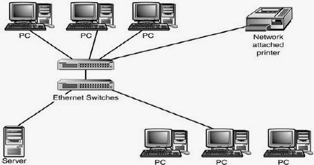
4.
Bus topology:
A
bus topology connects computers along a single or more cable to connect
linearly. A network that
uses a bus topology is referred to as a "bus network" which was the
original form of Ethernet networks. Ethernet 10Base2 (also known as
thinnet) is used for bus topology.

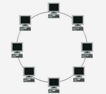
5.
Ring topology:
In
ring topology, each device has a dedicated point-to-point line configuration
only with two devices
on either side of it. A signal is passed along the ring in one direction, from
device to device
until it reaches its destination. Each device in the ring has a repeater. When
the devices receive
the signal intended for the other node, it just regenerates the bits and passes
them along. Ring
network passes a token. A token is a short message with the electronic address
of the receiver.
Each network interface card is given a unique electronic address, which is used
to identify the computer on the network.
Transmission
mode:
A
given transmission on a communications channel between two machines can occur
in several
different
ways.
Types
of Transmission mode
Simplex
Half Duplex
Full Duplex
A
simplex connection is a connection in which the data flows in
only one direction, from the
transmitter
to the receiver. This type of connection is useful if the data do not need to
flow in
both
directions (for example, from your computer to the printer or from the mouse to
your
computer...).
A
half-duplex connection (sometimes called an
alternating connection or semi-duplex) is a
connection
in which the data flows in one direction or the other, but not both at the same
time.
With
this type of connection, each end of the connection transmits in turn. This
type of
connection
makes it possible to have bidirectional communications using the full capacity
of the
line.
A
full-duplex connection is a connection in which the data flow in both
directions
simultaneously.
Each end of the line can thus transmit and receive at the same time, which
means
that
the bandwidth is divided in two for each direction of data transmission if the
same transmission medium is used for both directions
of transmission.

Categories
of networks:
LAN - Local Area Network
MAN - Metropolitan Area Network
WAN - Wide Area Network
Local
Area Network:
A
LAN connects network devices over a relatively short distance. A networked
office building, school,
or home usually contains a single LAN, though sometimes one building will
contain a few
small LANs (perhaps one per room), and occasionally a LAN will span a group of
nearby buildings.
In addition to operating in a limited space, LANs are also typically owned,
controlled, and managed by a single person or organization.
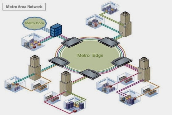
Metropolitan
Area Network:
Any
network spreading over a physical area larger than a LAN but smaller than a
WAN, such as a
city. A MAN is typically owned and operated by a single entity such as a
government body or large corporation.
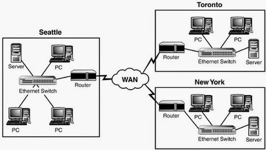
Wide
Area Network:
A
WAN is a network that spans more than one geographical location often
connecting separated LANs.
WANs are slower than LANs and often require additional and costly hardware such
as routers, dedicated leased lines, and complicated
implementation procedures.
OSI
and TCP/IP Models: Layers and their functions:
1.
Physical layer
2.
Data Link layer
3.
Network layer
4.
Transport layer
5.
Session layer
6.
Presentation layer
7.
Application layer
Physical
layer:
Establishment and termination of a connection
to a communications medium.
Participation in the process whereby the communication resources are effectively shared among multiple users. For example, contention resolution and flow control.
Modulation or conversion between the representation of digital data in user equipment and the corresponding signals transmitted over a communications channel. These are signals operating over the physical cabling(such as copper and optical fiber) or over a radio link.
Data
Link layer:
Framing
Physical Addressing
Flow Control
Error Control
Access Control
Media Access Control(MAC)
Network
layer:
Maintaining the quality of service requested by
the transport layer. The network layer performs network routing functions, and might also perform fragmentation and reassembly, and report
delivery errors. Routers operate at this layer, sending data
throughout the extended network and making the
Internet possible.
Transport
layer:
The transport layer provides transparent
transfer of data between end users.
It providing reliable data transfer services to
the upper layers.
The transport layer controls the reliability of
a given link through flow control, segmentation/desegmentation, and error control.
Some protocols are state- and
connection-oriented. This means that the transport layer
can keep track of the segments and retransmit those that fail.
can keep track of the segments and retransmit those that fail.
The transport layer also provides the
acknowledgement of the successful data transmission and sends the next data if no
errors occurred.
Session
layer:
The session layer controls the dialogues (connections) between computers. It establishes, manages and terminates the connections between the local and remote application. It provides for full-duplex, half-duplex, or simplex operation, and establishes checkpoint, adjournment, termination, and restart procedures. The OSI model made this layer responsible for graceful close of sessions, which is a property of the Transmission Control Protocol, and also for session checkpoint and recovery, which is not usually used in the Internet Protocol Suite. The session layer is commonly implemented explicitly in application environments that use remote procedure calls.
The session layer controls the dialogues (connections) between computers. It establishes, manages and terminates the connections between the local and remote application. It provides for full-duplex, half-duplex, or simplex operation, and establishes checkpoint, adjournment, termination, and restart procedures. The OSI model made this layer responsible for graceful close of sessions, which is a property of the Transmission Control Protocol, and also for session checkpoint and recovery, which is not usually used in the Internet Protocol Suite. The session layer is commonly implemented explicitly in application environments that use remote procedure calls.
Presentation
layer:
The presentation layer establishes context between application-layer entities, in which the higher-layer entities may use different syntax and semantics if the presentation service provides a mapping between them. If a mapping is available, presentation service data units are encapsulated into session protocol data units, and passed down the stack. This layer provides independence from data representation (e.g., encryption) by translating between application and network formats. The presentation layer transforms data into the form that the application accepts. This layer formats and encrypts data to be sent across a network. It is sometimes called the syntax layer.
The presentation layer establishes context between application-layer entities, in which the higher-layer entities may use different syntax and semantics if the presentation service provides a mapping between them. If a mapping is available, presentation service data units are encapsulated into session protocol data units, and passed down the stack. This layer provides independence from data representation (e.g., encryption) by translating between application and network formats. The presentation layer transforms data into the form that the application accepts. This layer formats and encrypts data to be sent across a network. It is sometimes called the syntax layer.
Application
layer:
The application layer is the OSI layer closest
to the end user, which means that both the
OSI application layer and the user interact
directly with the software application.
This layer interacts with software applications
that implement a communicating
component.
Application-layer functions typically include
identifying communication partners,
determining resource availability, and
synchronizing communication.
When identifying communication partners, the
application layer determines the identity
and availability of communication partners for
an application with data to transmit.
When determining resource availability, the
application layer must decide whether
sufficient network or the requested
communication exists.
In synchronizing communication, all
communication between applications requires cooperation
that is managed by the application layer
Comparison
of models:
1.
Open System Interconnection Model (OSI)
2.
Transport Control Protocol /Internet Protocol (TCP/IP)
a) There are seven
layers in OSI model where as TCP/IP has only five layers.
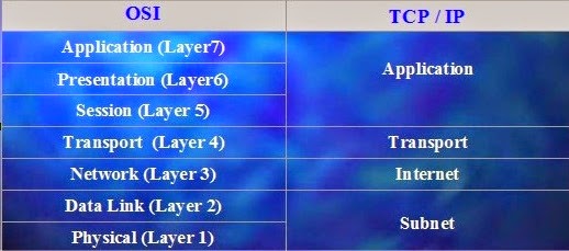
b)
In TCP /IP model three layers are combined in to a single application layer.

c)
The Session layer permits two parties to hold ongoing communications called a
session across a network. Not found in TCP/IP model. In TCP/IP, its characteristics are provided by
the TCP protocol.(Transport Layer)
d)
The Presentation Layer handles data format information for networked
communications.
This
is done by converting data into a generic format that could be understood by
both sides.
Not found in TCP/IP model. In TCP/IP, this function is provided by the Application
Layer.
e.g.
External Data Representation Standard (XDR) Multipurpose Internet Mail
Extensions
(MIME)
e)
The Application Layer is the top layer of the reference model. It provides a
set of interfaces for the applications to obtain access to networked services as well as access to
the kinds of network services that support applications directly.
OSI - FTAM,VT,MHS,DS,CMIP
TCP/IP - FTP,SMTP,TELNET,DNS,SNMP
Although
the notion of an application process is common to both, their approaches to constructing
application entities are different.
f)
Like all the other OSI Layers, the network layer provides both connectionless
and connection-oriented
services. As for the TCP/IP architecture, the internet layer is exclusively connectionless.
g)
Implementation of the OSI model places emphasis on providing a reliable data
transfer service, while the TCP/IP model treats reliability as an end-to-end problem.
h)
Each layer of the OSI model detects and handles errors, all data transmitted
includes check sums. The transport layer of the OSI model checks source-to-destination reliability.
i)
In the TCP/IP model, reliability control is concentrated at the transport
layer. The transport
layer handles all error detection and recovery. The TCP/IP transport layer uses checksums, acknowledgments, and timeouts to control transmissions and provides end-to-end
verification.
j)
Hosts on OSI implementations do not handle network operations (simple
terminal), but TCP/IP hosts participate in most network protocols.
k)
TCP/IP hosts carry out such functions as end-to-end verification, routing, and
network control. The TCP/IP internet can be viewed as a data stream delivery system involving intelligent hosts.
Digital
/Analog Transmission: Introduction
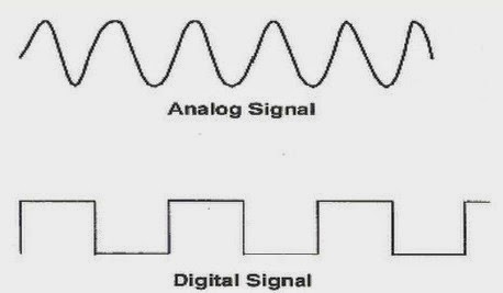
Analog
Signals:
An
analog or analogue signal
is any continuous signal for which the time varying feature (variable)
of the signal is a representation of some other time varying quantity, i.e.,
analogous to another
time varying signal. It differs from a digital signal in terms of small
fluctuations in the signal
which are meaningful. Analog is usually thought of in an electrical context;
however, mechanical,
pneumatic, hydraulic, and other systems may also convey analog signals.
Digital
Signals:
A
digital signal is a chemical signal that is a representation
of a sequence of discrete values (a quantified
discrete-time signal), for example of arbitrary bit stream, or of a digitized
(sampled and
analog-to-digital converted) analog signal. The term digital signal can refer
to
1.
A continuous-time waveform signal used in any form of digital communication.
2.
A pulse train signal that switches between a discrete number of voltage levels
or levels of light intensity, also known as a a line coded signal, for example a signal found in
digital electronics
or in serial communications using digital baseband transmission in, or a pulse code modulation (PCM) representation of a digitized analog signal.
A
signal that is generated by means of a digital modulation method (digital pass
band
transmission),
produced by a modem, is in the first case considered as a digital signal, and
in the second case as converted to an analog signal.
Interfaces
and Modems:
DTE-DCE
Interface:
Data
terminal equipment (DTE) is an end instrument that converts user
information into
signals
or reconverts received signals. These can also be called tail circuits. A DTE
device
communicates
with the data circuit-terminating equipment (DCE). It can be a terminal,
computer,
microcomputer, printer, fax machine or any other device that either generates
or
consumes
digital data.
Data
circuit-terminating equipment (DCE):
Any efficient component that either transmits or receives
data and information in the structure of
an analog or digital signal all the way through network. A
DCE takes information generated by a
DTE, changes them to a suitable signal, and then introduces
the signal onto the telecommunication link.

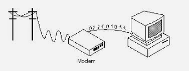
Modems :
A
modem (modulator-demodulator)
is a device that modulates an analog signal to digital signals,
and also demodulates such a signal to decode the transmitted information. The
goal is to
produce
a signal that can be transmitted easily and decoded to reproduce the original
digital data.
Modems can be used with any means of
transmitting analog signals.
Cable
modems:
To access Internet through a Cable TV network, Computer
Network requires a cable Modem. It has two interfaces on it one for computer and other for
Cable Network. This Modem makes a connection when it is turned on. Cable modems are always
retaining the connection (unless they are
switched off) because the cable operator does not charge for the duration of
connection.
When a cable Modem is switched on It scans the downstream
channel looking for a special packet periodically (special packet contains the modem
configuration and sender of this is the head end), after getting the packet, the new modem sends a
packet on one of the upstream channel.
Transmission
Media: Guided and unguided:
Transmission
media means any medium used for communication. It can be divided into two
categories’:
1. Guided media
2. Unguided media
Guide
media is that where we use any path for communication like
cables (coaxial, fibre optic,
twisted
pair) etc. Examples of guided media are:- Twisted Pair Cable, Co-axial Cable,
Optical
Fiber
Cable.
Unguided
media is also called wireless where not any physical path is
used for transmission.
Examples of unguided media are:- Microwave or
Radio Links, Infrared.

There
are three categories of guided media:
Twisted-pair
cable
Coaxial
cable
Fiber-optic
cable
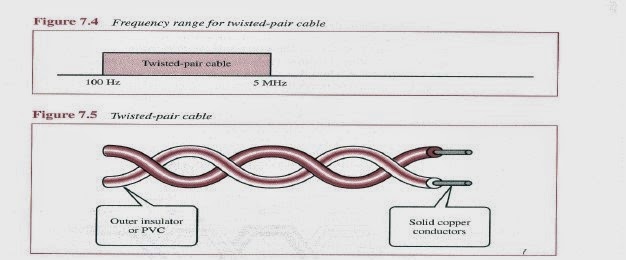
Twisted
pair consists of two conductors (normally copper), each with
its own plastic insulation,
twisted
together.
Twisted-pair
cable comes in two forms: unshielded and shielded.
The twisting helps to reduce the interference
(noise) and crosstalk.
Coaxial
cable carries signals of higher frequency ranges than
twisted-pair cable. It has inner conductor ,Insulator, Outer conductor metal
mesh, Insulator and plastic cover.

Applications:
Television distribution
Cable TV
Long distance telephone transmission
Can carry 10,000 voice calls simultaneously
Short distance computer systems links
Local area networks
More expensive than twisted pair, not as
popular for LANs
Fiber
optics cable:
Metal cables transmit signals in the form of
electric current.
Optical fiber is made of glass or plastic and
transmits signals in the form of light.
Light, a form of electromagnetic energy,
travels at 300,000 Kilometers/second (186,000 miles/second), in a vacuum.
The speed of the light depends on the density
of the medium through which it is
traveling ( the higher density, the slower the
speed).
Applications:Television distribution
Cable TV
Long distance telephone transmission
Can carry 10,000 voice calls simultaneously
Short distance computer systems links
Local area networks
More expensive than twisted pair, not as
popular for LANs

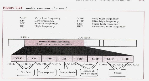
Unguided
media is also called wireless where not any physical path is
used for transmission.
Examples of unguided media are:- Microwave or
Radio Links, Infrared.

Transmission
impairments:
1.
Attenuation
2.
Distortion
3.
Noise
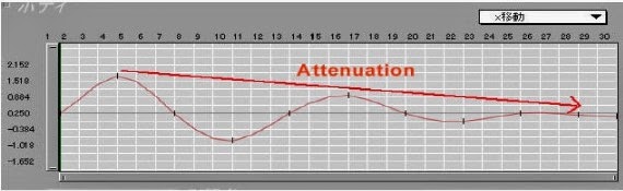
Attenuation:
In computer networking, attenuation is a loss of signal strength measured in decibels (dB). Attenuation occurs on networks
for several reasons:
Range - both wireless and wired transmissions
gradually dissipate in strength over longer
reaches
Interference - on wireless networks, radio
interference or physical obstructions like walls also
dampen communication signals
Wire size - on wired networks, thinner wires
suffer from higher (more) attenuation than
Distortion:
·
Various frequency components making up the signal arrive at the receiver with
varying delays.
·
Inter symbol Interference - the frequency components are delayed and they start
to interfere
With
the frequency components associated with the later bit.
·
Only in guided media.
· Propagation velocity varies with frequency.
Sources:
Thermal
Agitates the electrons in conductors, and is a function of the temperature. It
is often referred
to as white noise, because it affects uniformly the different frequencies.
- The thermal noise in a bandwidth W is where T=temperature, and k= Boltzmann's constant = 1.38 10-23 Joules/degrees Kelvin.
- Signal to noise ratio: Typically measured at the receiver, because it is the point where the noise is to be removed from the signal.
Inter
modulation Resulting from interference of different
frequencies sharing the same medium.
It
is caused by a component malfunction or a signal with excessive strength is
used.
For
example, the mixing of signals at frequencies f1
and f2 might produce energy at the
frequency
f1 + f2 .
This derived signal could interfere with an intended signal at frequency f1 + f2
.
Crosstalk
Foreign signal enters the path of the transmitted signal.
Impulse
Irregular disturbances, such as lightning, and flawed communication elements.
It is a
primary
source of error in digital data.
Throughput:
Throughput
refers to how much data can be transferred from one place to another in a given
amount
of time. This can be calculated in bits per second.
For
example, a hard drive that has a maximum transfer rate of 100 Mbps has twice
the
throughput
of a drive that can only transfer data at 50 Mbps. Similarly, a 54 Mbps
wireless
connection
has roughly 5 times as much throughput as a 11 Mbps connection. However, the
actual
data transfer speed may be limited by other factors such as the Internet
connection speed
and
other network traffic.
Propagation
speed and time, wavelength:
Propagation
is defined as the movement of waves across the medium defined within the limits
for
the nature of wave. The propagation speed varies accordingly depending upon the
various
characteristics
of the medium and waves. For instance, the electromagnetic wave, the mechanism
of
propagation involves mutual generation of periodically varying electric and
magnetic fields
and
is far more difficult to understand than sound.


Wave
Propagation Speed of a transmission medium is the speed at which a wave front
passes
through
the medium, relative to the speed of light. For optical signals, the velocity
factor is the
reciprocal
of the refractive index.
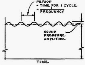
Time T
of a wave is the time that elapses between the arrival of two consecutive
crests (or
troughs)
at a certain location X. This definition is identical with the statement that
the period is
the
time the vibration at X takes to complete a full cycle from crest to trough to
crest. The period
of
a wave is given in seconds.
Wavelength λ,
is the distance between identical points in the adjacent cycles of a waveform
signal
propagated in space or along a wire, as shown in the illustration. In wireless
systems, this
length
is usually specified in meters, centimeters, or millimeters. In the case of
infrared, visible
light,
ultraviolet, and gamma radiation, the wavelength is more often specified in
nanometers(units of 10-9meter) or Angstrom units(units of 10-10
meter).

Wavelength
is inversely related to frequency. The higher the frequency of the signal, the
shorter
the
wavelength. If f is the frequency of the signal as measured in
megahertz, and w is the
wavelength
as measured in meters, then
w =
300/f
and
conversely
f =
300/w
Wavelength
is sometimes represented by the Greek letter lambda.
Shannon
Capacity:
It
is used to calculate the signal to noise ratio. The formula is:
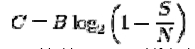
C
is measured in bits per second if the logarithm is taken in base 2, or n at s
per second if the natural
logarithm is used, assuming B is in hertz;; the signal and noise powers S
and N are measured
in watts or volts2, so the signal-to-noise ratio here is
expressed as a power ratio, not in decibels
(dB); since figures are often cited in dB, a conversion may be needed. For
example, 30 dB
is a power ratio of

Example:
Consider a noiseless channel with a bandwidth of 3000 Hz transmitting a signal
with
two
signal levels. The maximum bit rate can be calculated as:
Bit rate=2*3000*log2
2=6000bps
No comments:
Post a Comment