Telephony:
Multiplexing: Many to one, one to many
Multiplexing
is sending multiple signals from a single link. It means n number of inputs and
single
output. Multiplexing is sending multiple signals or streams of information on a
carrier at
the
same time in the form of a single, complex signal and then recovering the
separate signals at
the
receiving end.
There
are basically three types of multiplexing is used.
1.
WDM(wave division multiplexing)
2.
TDM (Time division multiplexing)
3.
FDM (Frequency division multiplexing)
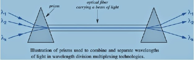
·In
optical transmissions, FDM is known as Wavelength Division Multiplexing (WDM).
·With
light different frequencies correspond to different colors.
·Several
transmissions can be sending over the same fiber by using different light
colors, and
combining
into a single light stream.
·Prisms are used as multiplexors and
demultiplexors.
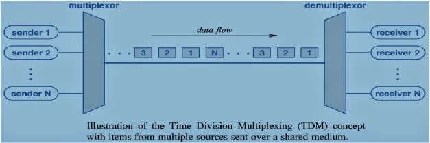
Time
Division Multiplexing (TDM):
·It
means dividing the available transmission time into time slots, and allocating
a different slot to each
transmitter.
·One method for transmitters to take turns is to
transmit in round-robin order.
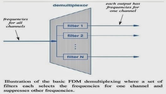
Frequency
Division Multiplexing (FDM):
·It
is the basis for broadcast radio.
·Several
stations can transmit simultaneously without interfering with each other
provided they use separate
carrier frequencies (separate channels).
·In
data communications FDM is implemented by sending multiple carrier waves over
the same copper wire.
·At
the receiver’s end, demultiplexing is performed by filtering out the
frequencies other than the one carrying
the expected transmission.
·Any of the modulation methods discussed before
can be used to carry bits within a channel.
Error
control:
Error
detection and correction:
Error:
·
Frame = m data bits + r bits for error control. – n = m + r.
·
Given the original frame f and the received frame f’, how many corresponding
bits differ?
–
Hamming distance (Hamming, 1950).
Parity
Bit:
·
Simple error detecting code.
·
Even- or odd parity.
·
Example:
–
Transmit 1011010.
–
Add parity bit 1011010 0 (even parity) or 1011010 1 (odd parity).
Hamming
Code:
·
Check bits in power-of-two positions.
·
Each check bit verifies a set of data bits.
·
A data bit is checked by multiple check bits.
·
Bits in positions that are power of 2 are check bits. The rest are data bits.
·
Each check bit used in parity (even or odd) computation of collection of bits.
–
Example: check bit in position 11, checks for bits in positions, 11 = 1+2+8. Similarly, bit 11 is
checked by bits 1, 2, and 8.
·
Parity computations:
–
11: 1, 2, 8 - 6: 2, 4
–
10: 2, 8 - 5: 1, 4
–
9: 1, 8 - 3: 1, 2
–
7: 1, 2, 4
Hamming
Code: Example 1
11
10 9 8 7 6 5 4 3 2 1
1:
1, 3, 5, 7, 9, 11
Data:
1001101 using even parity (counting from right to left).
11
10 9 8 7 6 5 4 3 2 1
2:
3, 6, 7, 10, 11
10011011
10011100101
Hamming
Code: Example 2
What
if instead of 1 0 0 1 1 1 0 0 10 1, receiver gets 1 0 0 1 0 1 0 0 1 0 1?
Receiver
takes frame received and re-computes check bits.
1:
3, 5, 7, 9, 11: 1, 1, 0, 1, 0, 1 => 1
2:
3, 6, 7, 10, 11: 0, 1, 1, 0, 0, 1 => 1
4:
5, 6, 7 : 0, 0, 1, 0 => 1
8:
9, 10, 11: 1, 0, 0, 1 => 0
11
10 9 8 7 6 5 4 3 2 1
0111
Result:
Bit in position 0 1 1 1 is wrong!
How
much code redundancy?
·
How many check bits needed, i.e., given m data bits, how many more bits (r) are
needed
to
allow all single-bit errors to be corrected?
–
Resulting frame is m + r.
–
(m+r+1) <= 2r.
–
Given m, then find r.
–
Example: If m = 7 (ASCII 7 code), minimum r is 4.
Hamming
Code: Example 7-bit
.
Hamming codes can only correct single errors.
.
But, to correct bursts of errors, send column by column.
Error
Detecting Codes
·
Typically used in reliable media.
·
Examples: parity bit, polynomial codes (CRC, or Cyclic redundancy Check).
Polynomial
Codes
·
Treat bit strings as representations of polynomials with coefficients 1’s and 0’s.
·
K-bit frame is coefficient list of polynomial with k terms (and degree k-1),
from xk-1to x0.
–
Highest-order bit is coefficient of xk-1, etc.
–
Example: 110001 represent x5 + x4 +x0.
·
Generator polynomial G(x).
–
Agreed upon by sender and receiver.
CRC:
·
Checksum appended to frame being transmitted.
–
Resulting polynomial divisible by G(x).
·
When receiver gets checksum frame, it divides it by G(x).
– If remainder, then error!
Cyclic
Redundancy Check
At
Transmitter, with M = 1 1 1 0 1 1, compute 2rM= 1 1 1 0 1 1 0 0 0 with G = 1 1
0 1
T
= 2rM + R [note G starts and ends with “1” R = 1 1 1 Transmit T= 1 1 1 0 1 1 1
1 1
Cyclic
Redundancy Check
At
the Receiver, compute:
Note
remainder = 0 no errors detected
CRC
Performance
·
Errors go through undetected only if divisible by G(x)
·
With “suitably chosen” G(x) CRC code detects all single-bit errors.
Flow
and error control: Different techniques to control the overflow
of data and different errors in
transmission
are called as Flow and error control techniques. Some techniques are as
Follows:
Simplex
Stop-and-Wait Protocol:
Simplex:
Data transmission in one direction. The receiver may not be always ready to
receive the next frame (finite buffer storage). Receiver sends a
positive acknowledgment frame to sender to transmit the next data frame.
Error-free communication channel assumed. No retransmissions used.

A
Simplex Positive Acknowledgment with Retransmission (PAR) Protocol. The
receiver may not be always
ready to receive the next frame (finite buffer storage). Noisy communication
channel; frames may be
damaged or lost. Frame not received correctly with probability P Receiver sends
a positive acknowledgment
frame to sender to transmit the next data frame. Any frame has a sequence
number,
either
0 or 1 Maximum utilization and throughput similar to protocol 2 when the
effects of errors are ignored.
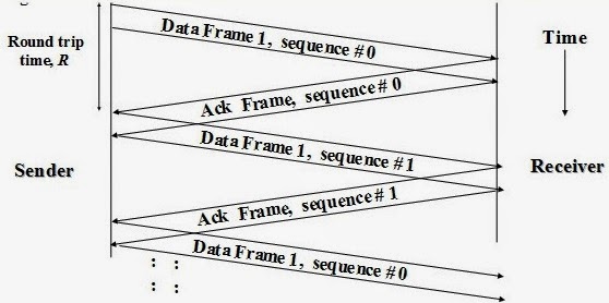
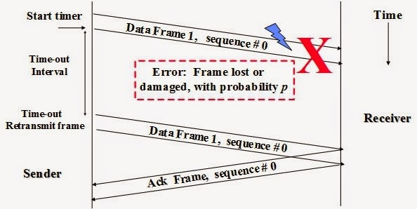
A
Simplex PAR Protocol (continued) Effect of Errors The sender starts a timer
when transmitting a data frame.
If data frame is lost or damaged (probability = p): Receiver does not send an
acknowledgment Sender times out and retransmits the data frame
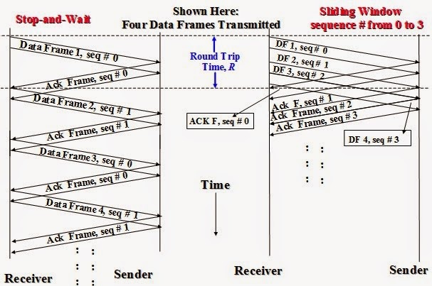
Flow
Control Sliding Window Protocols:
These
protocols allow both link nodes (A, B) to send and receive data and acknowledgments simultaneously.
Acknowledgments are piggybacked into an acknowledgment field in the data frame header
not as separate frames. If no new data frames are ready for transmission in a
specified time, a separate
acknowledgment frame is generated to avoid time-out. Each outbound frame
contains a sequence
number
ranging from 0 to 2 n-1 (n-bit field). N = 1 for stop-and-wait sliding window
protocols.
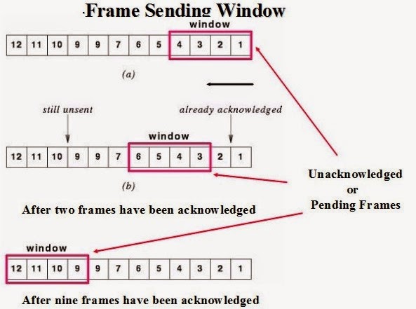
Sending
window: A set of sequence numbers maintained by the sender and correspond to
frame sequence numbers
of frames sent out but not acknowledged. The maximum allowed size of the
sending window w correspond
to the maximum number of frames the sender can transmit before receiving any acknowledgment without blocking (pipelining).
All frames in the sending window may be lost or damaged
and thus must be kept in memory or buffers until they are acknowledged. Sliding
Window Data
Link
Protocols
Receiving
window: A set of sequence numbers maintained by the
receiver and indicate the frames sequence
numbers it is allowed to receive and acknowledge. The size of the receiving
window is fixed at a
specified initial size. Any frame received with a sequence number outside the
receiving window is discarded.
The sending window and receiving window may not have the same upper or lower
limits or
have
the same size. When pipelining is used, an error in a frame is dealt with in
one of two ways:
Go back
n:
The
receiver discards all subsequent frames and sends no acknowledgments. The
sender times out and resends
all the discarded frames starting with faulty frame.
Selective
repeat:
The
receiving data link stores all good frames received after a bad frame. Only the
bad frame is retransmitted upon time-out by the sender.
Circuit
switching:
Circuit
switching is the most familiar technique used to build a communications
network. It is used
for ordinary telephone calls. It allows communications equipment and circuits,
to be shared among
users. Each user has sole access to a circuit (functionally equivalent to a
pair of copper wires)
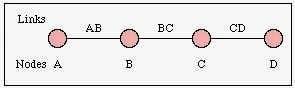
during network use. Consider communication between two points A and D in a
network.
The
connection between A and D is provided using (shared) links between two other
pieces of equipment, B and C.

A connection between two systems A & D formed from 3 links
Network
use is initiated by a connection phase, during which a circuit is set up
between source and
destination, and terminated by a disconnect phase. These phases, with
associated timings, are illustrated in the figure below.
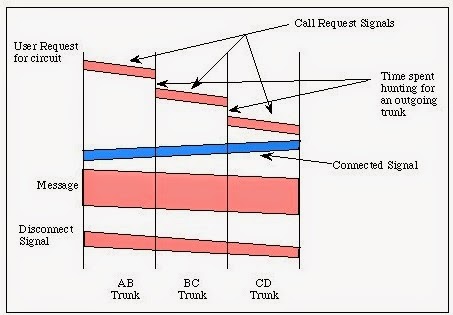
(Information
flows in two directions. Information sent from the calling end is shown in pink
and information
returned from the remote end is shown in blue)
After
a user requests a circuit, the desired destination address must be communicated
to the local switching
node (B). In a telephony network, this is achieved by dialing the number.
Node
B receives the connection request and identifies a path to the destination (D)
via an intermediate
node (C). This is followed by a circuit connection phase handled by the
switching nodes
and initiated by allocating a free circuit to C (link BC), followed by
transmission of a call request
signal from node B to node C. In turn, node C allocates a link (CD) and the
request is then
passed to node D after a similar delay.
The
circuit is then established and may be used. While it is available for use,
resources (i.e. in the intermediate
equipment at B and C) and capacity on the links between the equipment are dedicated
to the use of the circuit.
After
completion of the connection, a signal confirming circuit establishment (a
connect signal in the
diagram) is returned; this flows directly back to node A with no search delays
since the circuit
has been established. Transfer of the data in the message then begins. After
data transfer, the
circuit is disconnected; a simple disconnect phase is included after the end of
the data transmission.
Delays
for setting up a circuit connection can be high, especially if ordinary
telephone equipment is
used. Call setup time with conventional equipment is typically on the order of
5 to 25 seconds after
completion of dialing. New fast circuit switching techniques can reduce delays.
Trade-offs between circuit switching and other types of
switching depend strongly on switching times.
Packet
switching:
Packet
switching is similar to message switching using short messages. Any message
exceeding a
network-defined maximum length is broken up into shorter units, known as
packets, for transmission;
the packets, each with an associated header, are then transmitted individually through
the network. The fundamental difference in packet communication is that the
data is formed
into packets with a pre-defined header format (i.e. PCI), and well-known
"idle" patterns which
are used to occupy the link when there is no data to be communicated.
Packet
network equipment discards the "idle" patterns between packets and
processes the entire packet
as one piece of data. The equipment examines the packet header information
(PCI) and then
either removes the header (in an end system) or forwards the packet to another
system. If the
out-going link is not available, then the packet is placed in a queue until the
link becomes free. A packet network is formed by links which
connect packet network equipment.
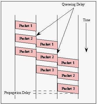
Packet-switched
communication between systems A and D
(The message in this case has been broken into three parts labeled 1-3)

A
connection between two systems A & D formed from 3 links
(The message in this case has been broken into three parts labeled 1-3)
There
are two important benefits from packet switching.
1.
The first and most important benefit is that since packets are short, the
communication links
between the nodes are only allocated to transferring a single message for a
short period
of time while transmitting each packet. Longer messages require a series of packets
to be sent, but do not require the link to be dedicated between the
transmission of each
packet. The implication is that packets belonging to other messages may be sent between
the packets of the message being sent from A to D. This provides a much fairer sharing
of the resources of each of the links.
2.
Another benefit of packet switching is known as "pipelining".
Pipelining is visible in the figure
above. At the time packet 1 is sent from B to C, packet 2 is sent from A to B; packet
1 is sent from C to D while packet 2 is sent from B to C, and packet 3 is sent
from A
to B, and so forth. This simultaneous use of communications links represents a
gain in efficiency;
the total delay for transmission across a packet network may be considerably less
than for message switching, despite the inclusion of a header in each packet
rather
than
in each message.
Message
switching:
Sometimes
there is no need for a circuit to be established all the way from the source to
the destination.
Consider a connection between the users (A and D) in the figure below (i.e. A
and D)
is represented by a series of links (AB, BC, and CD).
For
instance, when a telex (or email) message is sent from A to D, it first passes
over a local connection
(AB). It is then passed at some later time to C (via link BC), and from there
to the destination
(via link CD). At each message switch, the received message is stored, and a connection
is subsequently made to deliver the message to the neighboring message switch.
Message
switching is also known as store-and-forward switching since the messages are
stored at intermediate nodes en route to their
destinations.
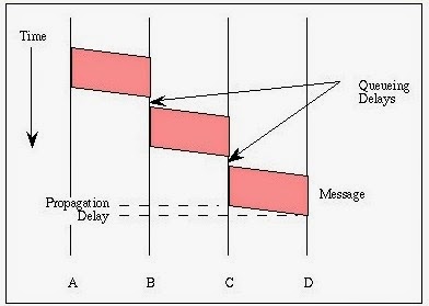
The
figure illustrates message switching; transmission of only one message is
illustrated for simplicity.
As the figure indicates, a complete message is sent from node A to node B when
the link
interconnecting them becomes available. Since the message may be competing with
other messages
for access to facilities, a queuing delay may be incurred while waiting for the
link to become
available. The message is stored at B until the next link becomes available,
with another queuing
delay before it can be forwarded. It repeats this process until it reaches its
destination.
Circuit
setup delays are replaced by queuing delays. Considerable extra delay may
result from storage
at individual nodes. A delay for putting the message on the communications link (message
length in bits divided by link speed in bps) is also incurred at each node en
route.
Message
lengths are slightly longer than they are in circuit switching, after
establishment of the circuit,
since header information must be included with each message; the header
includes information
identifying the destination as well as other types of information.
Most
message switched networks do not use dedicated point-to-point links and
therefore a call must
be set-up using a circuit switched network. The figure below illustrates the
use of message switching over a circuit switched network, in
this case using one intermediate message switch.
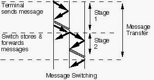
Message
switching using circuit switched connections between message switches.
Although
message switching is still used for electronic mail and telex transmission, it
has largely been
replaced by packet switching (in fact, most electronic mail is carried using
message switching
with the links between message switches provided by packet or circuit-switched networks).
Data
Link control protocols:
Line
discipline
Various
synchronous protocols manage communications on computer motherboards.
The
terms "synchronous" and "asynchronous" refer to the two
different styles of exchanging information in a digital system between two ports or devices. In both
styles, messages need to be organized in order to ensure that they are properly handled. Synchronous messages
typically use some sort of external clock to
match data exchange, while asynchronous messages simply
move at their own individual rates of speed, relying on established systems of rules to ensure proper
routing. All computer systems employ both methods
of communication and there are a number of different protocols for each.
synchronous
and asynchronous protocols overview:
File
Transfer Protocols
File transfer protocols are examples of asynchronous communication protocols. File Transfer Protocol (FTP), Apple Filing Protocol (AFP) and Bit Torrent are all examples of file transfer protocols. Typically, they divide data into small packets of bits, which are then sent over a network to a destination one at a time. A packet is not sent until the sender receives confirmation from the recipient that the previous packet has been received.
File transfer protocols are examples of asynchronous communication protocols. File Transfer Protocol (FTP), Apple Filing Protocol (AFP) and Bit Torrent are all examples of file transfer protocols. Typically, they divide data into small packets of bits, which are then sent over a network to a destination one at a time. A packet is not sent until the sender receives confirmation from the recipient that the previous packet has been received.
Email
There are three major protocols for sending and receiving email messages. Simple Mail TransferProtocol (SMTP) is an asynchronous protocol most often used to send email. Post Office Protocol (POP) and Internet Message Access Protocol (IMAP) are both asynchronous protocols most often used for receiving email.
There are three major protocols for sending and receiving email messages. Simple Mail TransferProtocol (SMTP) is an asynchronous protocol most often used to send email. Post Office Protocol (POP) and Internet Message Access Protocol (IMAP) are both asynchronous protocols most often used for receiving email.
World
Wide Web
The World Wide Web is entirely made up of asynchronous protocols. The most common is Hypertext Transfer Protocol (HTTP), though web sites also use Hypertext Transfer Protocol Secure (HTTPS) among other protocols for exchanging information over the web.
The World Wide Web is entirely made up of asynchronous protocols. The most common is Hypertext Transfer Protocol (HTTP), though web sites also use Hypertext Transfer Protocol Secure (HTTPS) among other protocols for exchanging information over the web.
Serial
Peripheral Interface Bus
The Serial Peripheral Interface Bus (SPI) is a synchronous communication protocol used to link computers within a formal system. Typically, computers are linked into a master-slave relationship where one computer is the "master" controlling the other "slaves."
The Serial Peripheral Interface Bus (SPI) is a synchronous communication protocol used to link computers within a formal system. Typically, computers are linked into a master-slave relationship where one computer is the "master" controlling the other "slaves."
Inter-Integrated
Circuit
Inter-Integrated Circuit (I2C) is a synchronous protocol for connecting devices such as drives, input/output devices and printers to a motherboard or other computer control system. I2C is a very common method for linking peripheral devices to computers, and has become the basis for a number of other technological systems such as the System Management Bus (SMB) that controls power to computer motherboards.
Inter-Integrated Circuit (I2C) is a synchronous protocol for connecting devices such as drives, input/output devices and printers to a motherboard or other computer control system. I2C is a very common method for linking peripheral devices to computers, and has become the basis for a number of other technological systems such as the System Management Bus (SMB) that controls power to computer motherboards.
ISDN:
Integrated
Services Digital Network (ISDN) is a set of communication standards for digital
transmission of
voice, video, data, and other network services over the traditional circuits of
the public switched telephone
network.
Historical
outline:
It
was first defined in 1988 in the CCITT red book. Prior to ISDN, the telephone
system was viewed as a way
to transport voice, with some special services available for data. The key
feature of ISDN is that it integrates
speech and data on the same lines, adding features that were not available in
the classic telephone
system. There are several kinds of access interfaces to ISDN defined as Basic
Rate Interface (BRI),
Primary Rate Interface (PRI), Narrowband ISDN (N-ISDN), and Broadband ISDN
(B-ISDN).
Subscriber’s
access:
ISDN
is a circuit-switched telephone network system, which also provides access to
packet switched networks,
designed to allow digital transmission of voice and data over ordinary
telephone copper wires, resulting
in potentially better voice quality than an analog phone can provide. It offers
circuit-switched connections
(for either voice or data), and packet-switched connections (for data), in
increments of 64 kilobit/s.
A major market application for ISDN in some countries is Internet access, where
ISDN typically provides
a maximum of 128 kbps in both upstream and downstream directions. Channel
bonding can achieve
a greater data rate; typically the ISDN B-channels of three or four BRIs (six
to eight 64 kbps channels)
are bonded.
ISDN
Layers:
Layer
1
ISDN
physical layer (Layer 1) frame formats differ depending on whether the frame is
outbound (from terminal
to network) or inbound (from network to terminal).
In
the figure frames are 48 bits long, of which 36 bits represent data. The bits
of an ISDN physical layer frame
are used as follows:
- F - Provides synchronization
- L - Adjusts the average bit value
- E - Ensures contention resolution when several terminals on a passive bus contend for a channel
- A - Activates devices
- S - Is unassigned
- B1, B2, and D - Handle user data

Multiple
ISDN user devices can be physically attached to one circuit. In this
configuration, collisions can result
if two terminals transmit simultaneously. Therefore, ISDN provides features to
determine link contention.
When an NT receives a D bit from the TE, it echoes back the bit in the next
E-bit position.
The
TE expects the next E bit to be the same as its last transmitted D bit.
Terminals
cannot transmit into the D channel unless they first detect a specific number
of one’s (indicating
"no signal") corresponding to a pre-established priority. If the TE
detects a bit in the echo (E) channel
that is different from its D bits, it must stop transmitting immediately. This
simple technique ensures
that only one terminal can transmit its D message at one time. After successful
D-message transmission,
the terminal has its priority reduced by requiring it to detect more continuous
ones before transmitting.
Terminals cannot raise their priority until all other devices on the same line
have had an opportunity
to send a D message. Telephone connections have higher priority than all other
services, and signaling
information has a higher priority than non signaling information.
Layer
2
Layer
2 of the ISDN signaling protocol is Link Access Procedure, D channel (LAPD).
LAPD is similar to High-Level
Data Link Control (HDLC) and Link Access Procedure, Balanced (LAPB). As the
expansion of
the LAPD acronym indicates, this layer is used across the D channel to ensure
that control and signaling information flows and is received
properly.
Figure: LAPD Frame Format Is Similar to That of HDLC and LAPB
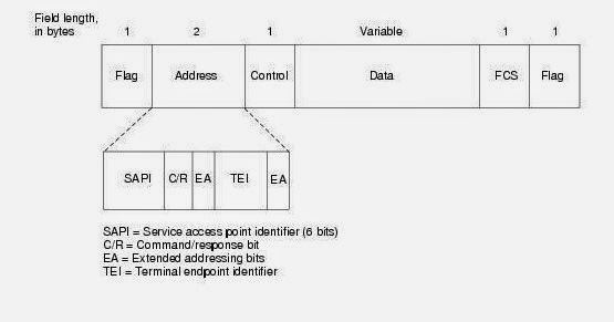
The
LAPD Flag and Control fields are identical to those of HDLC. The LAPD Address
field can be either 1
or 2 bytes long. If the extended address bit of the first byte is set, the
address is 1 byte; if it is not set, the address
is 2 bytes. The first Address-field byte contains the service access point
identifier (SAPI), which identifies
the portal at which LAPD services are provided to Layer 3. The C/R bit
indicates whether the frame
contains a command or a response. The Terminal Endpoint Identifier (TEI) field
identifies either a single
terminal or multiple terminals. A TEI of all ones indicates a broadcast.
Layer
3
Two
Layer 3 specifications are used for ISDN signaling: ITU-T (formerly CCITT)
I.450 (also known as ITU-T
Q.930) and ITU-T I.451 (also known as ITU-T Q.931). Together, these protocols
support user-to-user,
circuit-switched, and packet-switched connections. A variety of
call-establishment, call-termination, information,
and miscellaneous messages are specified, including SETUP, CONNECT, RELEASE, USER
INFORMATION, CANCEL, STATUS, and DISCONNECT. These messages are functionally similar to those provided by the X.25 protocol.
Figure: An ISDN Circuit-Switched Call Moves through Various Stages to Its Destination

Broadband ISDN: Broadband Integrated Services Digital Network (BISDN)
Broadband
Integrated Services Digital Network (BISDN or Broadband ISDN) is designed to
handle high-bandwidth applications. BISDN currently uses ATM
technology over SONET-based transmission circuits to
provide data rates from 155 to 622Mbps and beyond, contrast with the
traditional narrowband ISDN(or
N-ISDN), which is only 64 Kbps basically and up to 2 Mbps.
The
designed Broadband ISDN (BISDN) services can be categorized as follows:
Conversational services such as telephone-like services, which was also supported by ISDN. Also the additional bandwidth offered will
allow such services as video telephony, video mail, as well as
multi-media mail and traditional electronic mail. Retrieval services which provides access to (public) information stores, and information
is sent to the user on demand only.
No user control of presentation. This would be
for instance, a TV broadcast, where the user can choose simply either to view or not.
User controlled presentation. This would apply
to broadcast information that the user can partially control.
No comments:
Post a Comment